Audio Synthesis Blocks

Sections
Concept
Synthesis Blocks are a teaching tool that demonstrates how additive synthesis can be used to generate tones for electronic instruments.
Synthesis Blocks use additive synthesis, which creates timbre by adding together multiple pure sine tones. In its simplest form, it contains a fundamental tone and a series of harmonic tones which decrease in volume. More complex forms of additive synthesis use envelopes to adjust the volume of each individual harmonic. (More information on additive synthesis.)
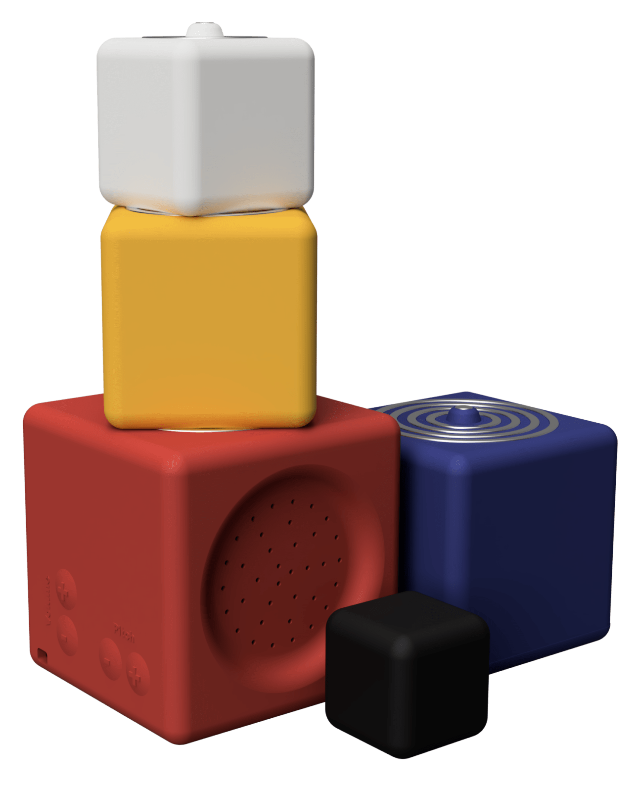
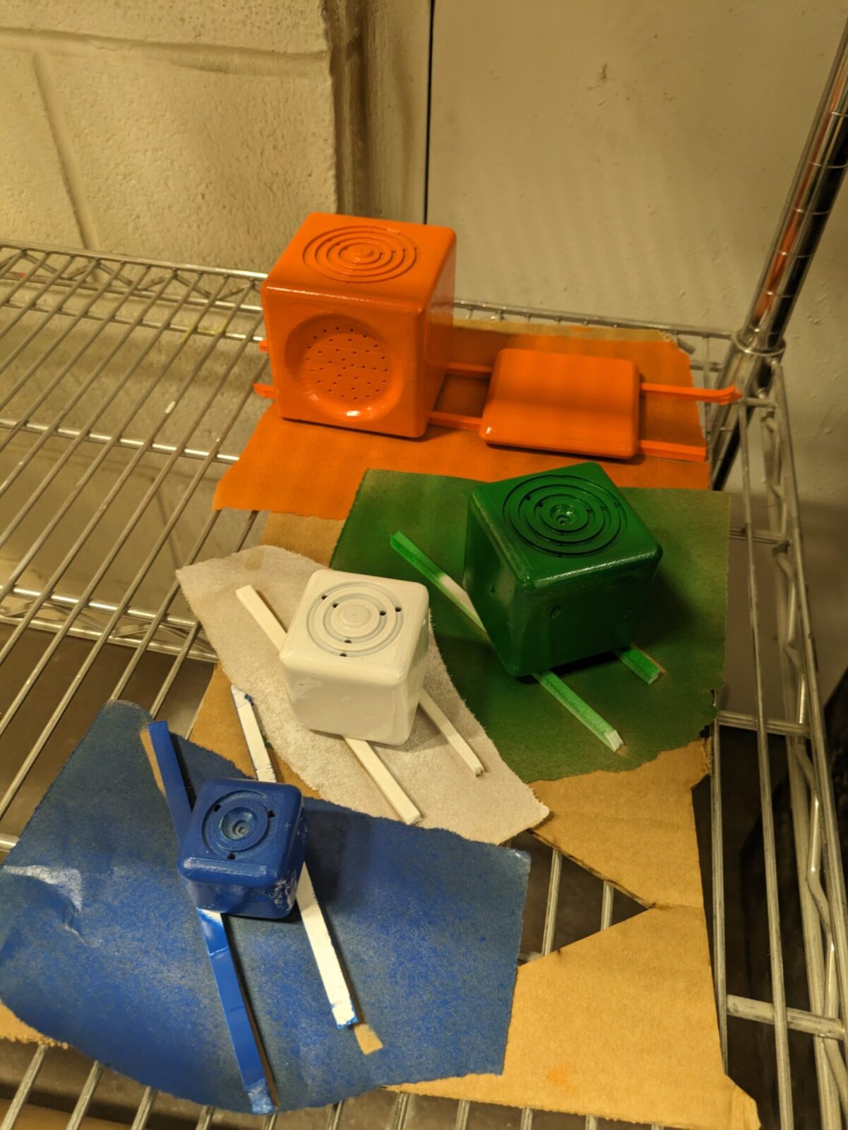
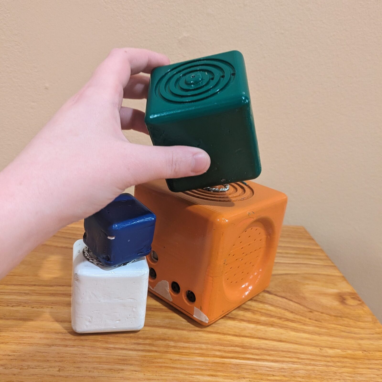
I will be demonstrating this principle using blocks:
- The base block will play a pure sine-wave fundamental tone
- With each additional block that is stacked, a new harmonic is added
- By stacking only certain blocks, different combinations of harmonics can be achieved
Method
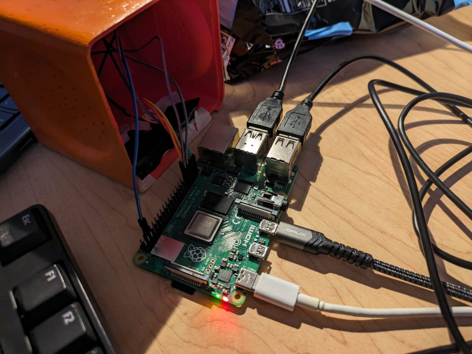
My prototypes use a Raspberry Pi with Python3 and Pure Data. Pure Data is a visual coding language for making computer generated music. It is the open source version of Max/MSP by the same developer.
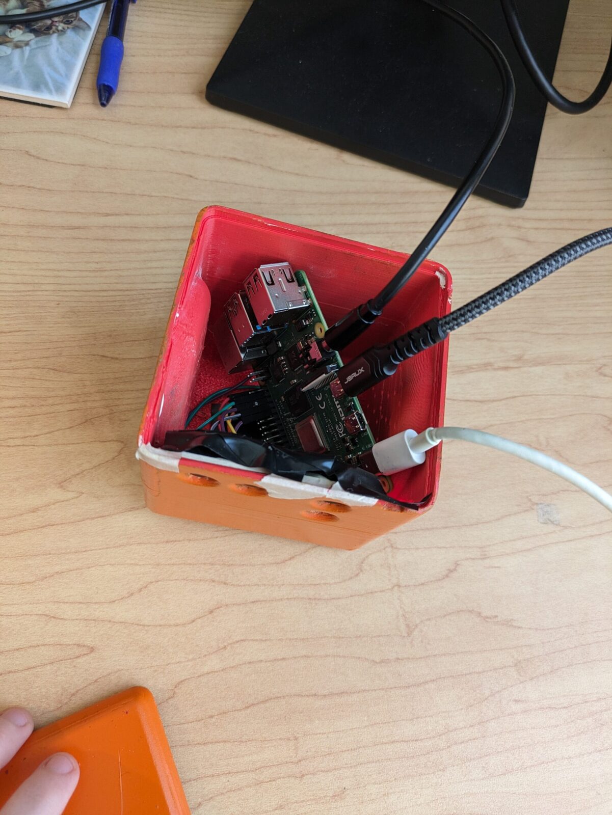
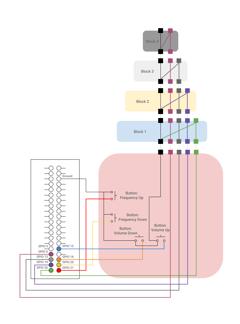
The microprocessor, speaker, and all active electronics are housed in the base block. The additional blocks only contain connecting wires.
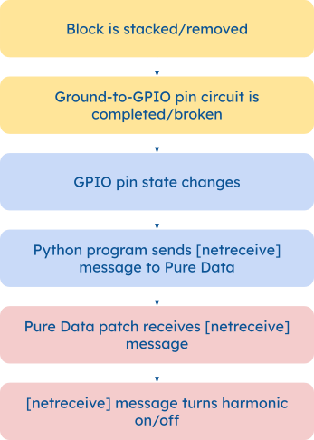
When the blocks connect to Raspberry Pi GPIO pins, a Python program sends a message to a Pure Data synthesizer patch.
CAD Designs


Initial Prototypes
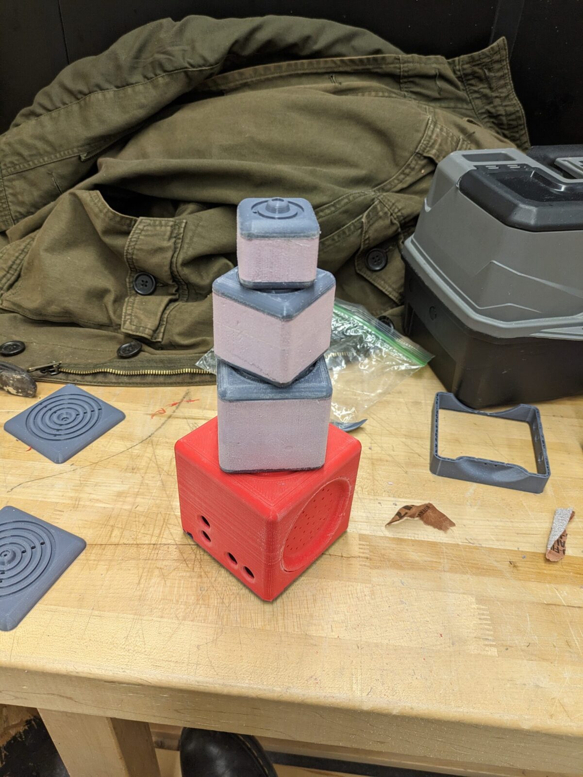
This initial prototype of the Synthesis Blocks was made to test the software elements of the project and demonstrate the functionality.
In this prototype, loose connector wires take the place of several of the blocks. This effectively demonstrates the functionality, as setting the block simply connects the ground to the GPIO pin. In the finished product, the connecting wire would run through the blocks and make a connection through the metal rings.
The bottom cap is not on in the demonstration because the HDMI and audio outputs are being used for demonstration purposes. The program can be run without a GUI, and in a more finalized version, would have an internal speaker.
Electronics
Ground connects to each button, then goes through the center of the blocks
For each block, the outermost ring is connected into the ground, which completes the circuit when the block is placed
The blocks work as switches: when placed, the outermost ring of each block connects with the ground, which identifies the block placed and changes the GPIO pin state.
Python
In order to recognize and react to the GPIO pin state changes, I used a Python program running on the Raspberry Pi. The program checks for a change in the GPIO pin state then sends a message relaying the information to a Pure Data synthesizer patch using “pdsend”. The “pdsend” utillity is used to send commands to Pure Data.
Example code for Block 1
Define & Set Up Pins
B1=26

GPIO.setup(B1, GPIO.IN, pull_up_down=GPIO.PUD_UP)

previous_B1_state = GPIO.input(B1)
Define send2Pd(message):
def send2Pd(message=""):

   os.system("echo '" + message + "' | pdsend 3000")
Start loop
while True:

   time.sleep(0.01)

   B1_state = GPIO.input(B1)
(Within Loop) Check GPIO pin states, then, if they have changed, check current state, and send correlating send2Pd(message)
if B1_state != previous_B1_state:

   #port = '3000'

   previous_B1_state = B1_state

   if B1_state == GPIO.LOW:

       #Click action goes here

       message = '0 1;'

       send2Pd(message)

   else:

       #Release action goes here

       message = '0 0;'

       send2Pd(message)
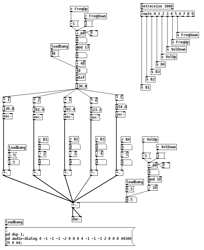
Pure Data
The Pure Data [netreceive] object receives a message from produced by the Python script and completes the corresponding action.
[loadbang] object sets up audio devices & settings (for ease of set up and also so that the patch can run without a GUI)
The patch uses 5 oscillators set to harmonics of a fundamental tone
The harmonics are turned on or off by the [netreceive] messages triggered by stacking a block
The frequency of the fundamental and the overall volume are controlled by the [netreceive] messages from up/down buttons
pd object [netreceive 3000] receives a two number message from the send2pd function in the Python script
The first number (0-9) routes it to the corresponding oscillator or button
The second number (1 or 0 for oscillators and 1 or -1 for buttons) is the message sent to the oscillator or button counter